The PVE pneumatic lift, also called a vacuum lift, does without a shaft, pit or machine room, yet the factory sets a few clear requirements for the house. We have compiled them from the installation requirements on the factory website (2024 edition) and converted them to metric units.
Base for a pneumatic lift
The lift stands on the finished floor of the lowest floor and is self-supporting. The floor must be perfectly level. The weight of the lift depends on the model and the height: approximately from 0.4 t for the smallest model to over 1.5 t for the largest, plus the weight of the passengers. So during the site survey we find out what is under the floor (a ground slab, a floor slab, underfloor heating) and recommend reinforcement where needed.
Two installation methods
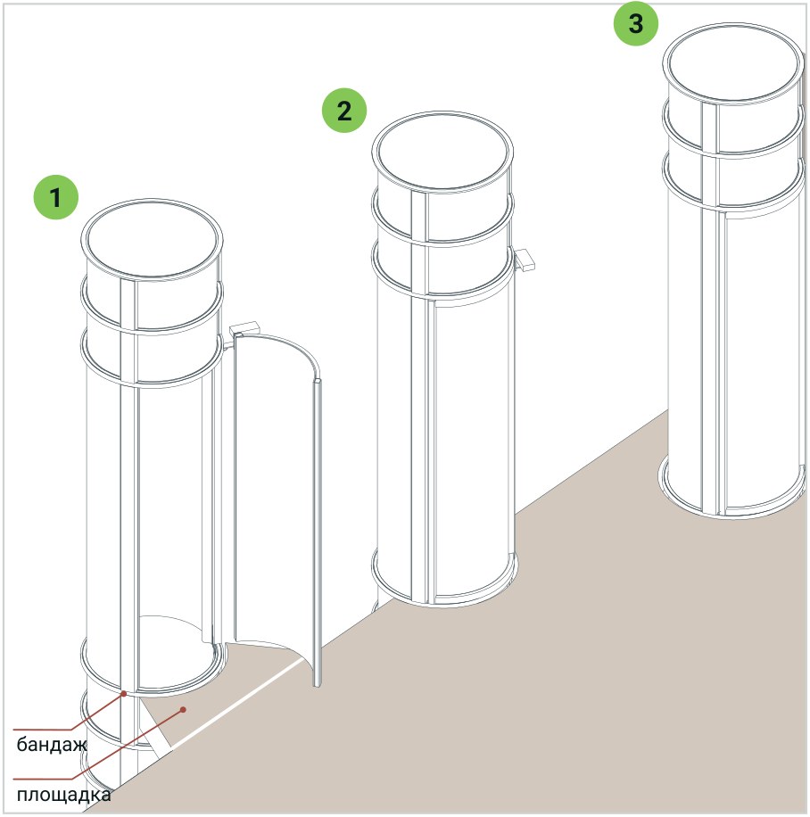
- Through the floor. A finished opening 50 mm larger than the cylinder is made in each floor. The openings must be exactly one above the other and no closer than 50 mm to a wall.
- Against a balcony or gallery. The lift stands in a double-height space, in a stairwell or beside a mezzanine, and no opening is needed. A landing shaped to the cylinder is made at the upper level, and the lift is fixed to the floor slab with a retaining band. The factory also offers a ready-made aluminium landing in the colour of the lift.
| Dimension, mm | PVE30 | PVE37 | PVE52 | The Cube |
|---|---|---|---|---|
| External size of the lift | Ø 750 | Ø 933 | Ø 1338 | 914 x 914 |
| Floor opening | Ø 813 | Ø 991 | Ø 1389 | 965 x 965 |
| Landing at the balcony, widest point | 775 | 953 | 1359 | per factory drawing |
Floor heights
- Lower floors: at least 2.34 m floor to floor and 2.06 m floor to ceiling.
- Top floor: at least 2.72 m if the head unit sits on the cylinder.
- Top floor: at least 2.47 m if the head unit is remote.
- The factory considers a lower height separately for each house.
Where the head unit goes
The head unit with the turbines, that is, the lift's vacuum pump, can sit on top of the lift or be installed remotely. This determines the top floor height required and the noise in the house: the turbines can be heard while the lift goes up, and the further the head unit is from the rooms, the quieter it is.
- On the cylinder. The standard version and the simplest installation: power is brought to the top of the lift.
- On the cylinder with an acoustic enclosure. The same head unit with a sound-absorbing enclosure.
- Remote, inside the house. In the attic, a storage room or a plant room, up to 9 m from the lift. It is connected to the top of the lift by two 100 mm PVC pipes or flexible hoses (one pipe on the PVE30). Space for the head unit: 0.86 x 0.61 x 0.61 m.
- Remote, outdoors. In a fibreglass enclosure outside the house, up to 9 m from the lift. The controller stays in a heated room. This is the quietest option.
Electrics and temperature
- A dedicated 220-240 V single-phase line, 50/60 Hz, earthed and with a 30 A circuit breaker (40 A for the PVE52).
- Power is brought to the top of the lift or to the place where the remote head unit stands.
- The factory strongly recommends a voltage stabiliser: voltage surges damage the electronics, and the warranty does not cover such damage.
- The lift works in a heated room. It is not used at temperatures below +18 °C, so an unheated garage, a veranda or the outdoors are not suitable.
How a pneumatic lift is brought in and installed
The cylinder sections, 2.34 m high, are brought in through a door or a window. A lifting hook is needed in the ceiling above the lift: rated for 680 kg for the PVE30, 816 kg for the PVE37 and The Cube, and 1451 kg for the PVE52. If there is no hook, the top floor must be at least 2.77 m high.
- Site survey: we come to the site, measure the floor heights, check the base and choose where the lift and the head unit will stand.
- Factory drawing: the factory builds the lift to your floor heights. We agree the drawing with the opening and landing dimensions with you.
- Preparation: openings in the floors or landings, a dedicated power line, a route for bringing in the sections.
- Installation: we stack the sections one on top of another, connect the head unit and adjust the stops.
- Handover and service: we show you how to use the lift and what to do in a power cut. After that we inspect the lift on schedule.


Maintenance after installation
The factory recommends inspecting the lift every 6 months. The main car seal is replaced roughly every 5 years or after 15,000 trips. There is no oil or grease in the lift. Manufacturer's warranty: 1 year. We state the manufacturing and delivery time in the quotation: it depends on the model and the configuration.
What we check during the site survey
- Whether the floor of the lowest floor is level and what is under it.
- The heights of all floors and of the top-floor ceiling.
- What runs through the floors where the openings will be: beams, pipes, wiring.
- How to bring in the 2.34 m high sections: doors, windows, stairs.
- Where to run the dedicated power line from and where to put the head unit.
- Whether the room is warm in winter: no lower than +18 °C.
The site survey and model selection start with a request: leave one on the website or call +38 (050) 585-39-28. See also the overview of PVE pneumatic lifts, the PVE30, PVE37, PVE52 and The Cube models and the "PVE - LIFTPORTAL" catalogue (PDF).
